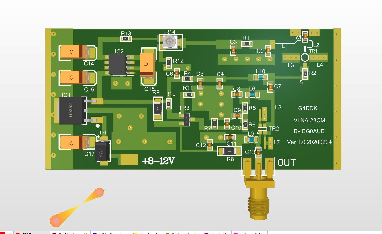
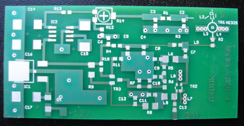
Since the G4DDK VLNA kit is no longer available, I tried to copy the classic version, hoping for success
由于G4DDK VLNA套件不再可用,我尝试复制经典版本,希望成功
看一下BG0AUB发布的电路图

[v_notice]
Product information
Anglian 3L Transverter
3L Kits are available. I produce the kits in small batches.
Anglian 4 transverter
Anglian 4 Kits are available. Currently ( March 2018) numbers are limited.
Iceni 70cm transverter
Initially, these will only be available as a short kit whilst I sort out the logistics of dealing with the many SMD parts used in the kit.
VLNA
VLNA is now synonymous with the G4DDK low noise preamplifier for 23cm and 13cm. A version is also available for 9cm. It stands for Very Low Noise Amplifier. The name is not unique, but has become synonymous with the G4DDK preamp.
The VLNA has been remarkably successful since it's introduction, over lunch, at the 2007 Weinheim VHF meeting in Germany! The current serial number is now well over 2400. This does not mean that is the number sold, but it's not far off!
When developing the VLNA for 23cm EME experience was drawn from the design of WA5AGO and work by WA5LUA (now W5LUA). My contribution was to realise that the ATF54143 would make a better, low noise, higher dynamic range second stage than existing designs.
The original VLNA was meant for 23cm only. The noise matching was optimised for 1296MHz operation. It wasn't long before I discovered that the design could be stretched to 2320MHz and later to 3400MHz and down to 432MHz. All from one PCB design!
After a board redesign the Issue 2 board has been in constant production for about 10 years. One change that has had to be introduced is the the original ATF54143 is no longer manufactured and it is now replaced by the (almost) identical SAV-541+
It would be unfair not to recognise the contribution by RW3BP. Sergie did some great work on the original VLNA and improved its input match, lowered the noise figure and improved its stability. However, not all of Sergie's ideas are practical from a production point of view and so the VLNA has adopted just some of his ideas including use of the MGF4919 as the first stage. In practice this has provided a lower noise figure than the previous NE32584 and a noise figure of around 0.25dB is now typical. Previously it was time consuming, but possible, to get below 0.30dB and occasionally to 0.25 and even down to 0.22dB. Now, these numbers are open to debate in view of the uncertainties of accurate and repeateably measuring such low noise figures with any great meaning. However after many hundreds of measurements in Europe, and North America, it can be claimed that 0.25dB is achievable and on-air results in EME operation have confirmed the extremely low noise figures achieved by builders of the VLNA.
VLNA9 uses a different input device in order to achieve a noise figure of below 0.4dB.
A word of caution. The VLNA23 has a very high gain of around 37dB at 1296MHz, with the absolute gain peak of around 40dB occuring at about 1.05GHz. This is intentional and a result of the low noise input arrangement. It is quite normal in low noise designs. But, it does mean that you need to be careful when using the VLNA23 not to pick up nearby 900MHz Mobile Base stations as the amplified output from the VLNA may cause gain compression (blocking) in the later stages of the receive chain. The gain of the VLNA13 and 9 are a bit lower, by about 10dB, so don't tend to suffer this problem. The gain of the VLNA70 is deliberately tailored to be no more than about 36dB in order to reduce blocking from nearby digital TV transmitters. You should carefully consider whether you need the full gain of the VLNA23 when attempting to use it with terrestrial systems and it is recommended that a 15-20dB pad should be inserted after the VLNA23 and before the following receiver. This may also be necessary with the VLNA70.
So, now you are familiar with the number one 23 and 13cm low noise preamplifier, go to the price list and see if you would like to buy one from me. You can choose the band, kit and how you want to pay. I don't have an on-line shop so you will need to e-mail me to ask about availability. e-mail at the bottom of the page. I accept either Paypal (prefered) or bank transfer. In the case of bank transfer I will need to send you an invoice first.
For Paypal I will ask for your callsign (if appropriate) and shipping address to be added in the Paypal payments comments box. This is for my reference, even if you have already given me these details.
Note, this is the old, original, PCB from 2007
Home
SPF Amplifier
Not currently available
These amplifier kits are based on the popular boards by WA5VJB.
The SPF Amplifier components are optimised for the frequency range 400 to 2400MHz
Board kits are available for SMA input and output as shown below. These boards have no provision for extra RF path filtering
The smaller cable terminated boards are in extremely short supply at present.
The SPF Amplifier performance is shown in the SPF Amp PDF

PGA wideband amplifiers
If you want high dynamic range, low noise and widebandwidth, then the PGA Amp is the one to choose. Currently PCB levels are very good.

PGA Amp PCB This board is also available ready assembled, to order.
The PGA Amplifier kit provides a noise figure of below 0.5dB at 2m and 70cm, rising to 0.8dB at 23cm. However, the wideband frequency response of the PGA Amplifier means that it is important to use a filter either at the input or output of the amplifier IF IT IS CONNECTED TO AN ANTENNA. This makes the wideband PGA amplifier better suited to use within equipment to boost levels, reduce noise figure or just add gain. Full details of performance are published in the PDF
The PGA144 (described next) is a truly Contest grade 2m preamplifier and already incorporates the necessary filtering.
Home
PGA144
This is a fully filtered, low noise, high dynamic range contest grade preamplifier. Unlike other PGA based amplifiers the main filtering is at the input, with a broader band pass filter at the output. Two metre receivers are prone to blocking from nearby Band 2FM broadcast transmitters in the 87.5 to 108MHz frequency range. Whilst the FM transmitter will be unlikely to trouble the PGA144, the following receiver may become 'blocked' by high level Band 2 signals. Blocking or gain compression manifests itself as a reduction in sensitivity and can even produce intermodulation artifacts on top of wanted signals. The 130MHz high pass filter and notch arrangement used in the PGA144 was devised by G4SWX as a combined Band 2 notch and 2m bandpass filter that reduces the Band 2 signals to 'safe' levels whilst introducing minimal input loss at 2m. Hence the low noise figure of the PGA device is maintained. The PGA144 is suitable for EME where the very low noise figures often quoted for some designs cannot be used in practice due to high local noise levels, but where 0.5-0.6dB is more than adequate and the PGA144 very high dynamic range allows operation where some other low noise, low dynamic range, preampliers can be a problem.
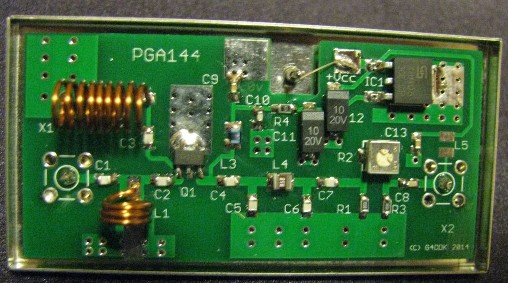
The PGA144 has built in gain adjustment, supply regulator, provision for over-coax powering and SMA input and output connectors.
Please note, the PGA144 does not incorporate any antenna switching relays. You need to provide these yourself!
PGA432
Following on from the successful PGA144 preamplifier the PGA432 uses the same PCB circuit techniques to deliver a low noise, high dynamic range preamplifier for the 70cm band. A deep notch at 144MHz is incorporated as protection against strong 144MHz (2m amateur band) signals such as might be experienced when operating on 70cm during a multiband contest or when using satellite Mode J with the user uplink on 144MHz. The notch is over 60dB down on the wanted 432/435MHz at the preamplifier output.
The input third order intercept of the PGA432 has been independently measured by one of our well known and respected VHF contesters and GURU at +19dBm. This is an exceptional figure for a 432MHz IIP3 and with the very low noise figure and proper input filtering, an excellent choice for those situations where you have problems from nearby out of band transmitters.

[/v_notice]
Comments NOTHING